
Wire an ESP32 or Arduino to a Delta DVP PLC over RS-485, switch COM2 to Modbus RTU, and read or write D, M and Y...
Latest posts
-
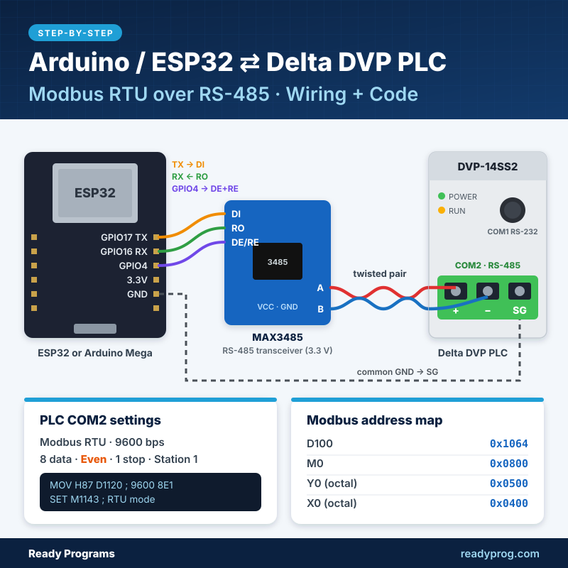 How to Connect an Arduino or ESP32 to a Delta DVP PLC with Modbus RTU (RS-485)Read more
-
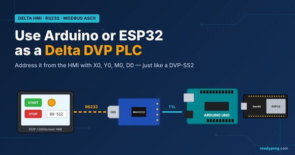 Use Arduino or ESP32 as a Delta DVP PLC: Control It from a Delta HMI via RS232Read more
Turn an Arduino or ESP32 into a Delta DVP-SS2 PLC that your Delta HMI talks to over RS232. Design screens with X0,...
-
 How AI Dictates When Mechanical Parts Must Be Replaced in Automotive and AerospaceRead more
Discover how Edge AI and microcontrollers like the ESP32 are revolutionizing vehicle and aerospace diagnostics. By...
-
 How to Choose a Graduation Project Idea in Computer Science & Software Engineering (2026 Guide)Read more
A practical, step-by-step guide to choosing a winning graduation project idea in computer science or software...
-
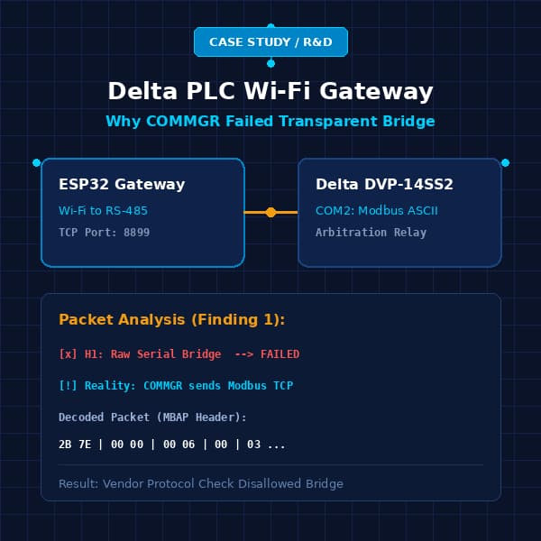 A Failed Wi-Fi Gateway for a Delta PLC: What a Packet Log Taught Me About Unverified AssumptionsRead more
I designed a sub-$7 wireless programming gateway for a Delta DVP-14SS2 PLC (ESP32, RS-485 transceiver, arbitration...
Blog categories
Search in blog
Archived posts
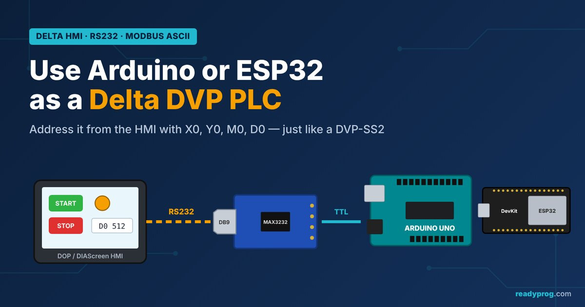
Use Arduino or ESP32 as a Delta DVP PLC: Control It from a Delta HMI via RS232
You have a Delta HMI (DOP-100 / DOP-B series) on your desk, but no PLC. Or you have a project where a full PLC is too expensive and an Arduino or ESP32 would do the job. The problem: the HMI only talks to controllers that exist in its driver list, and the standard "Modbus" route forces you to type raw addresses like 4x1001.
In this guide I show you a cleaner approach: we make the Arduino or ESP32 behave exactly like a Delta DVP-SS2 PLC. In DOPSoft or DIAScreen you simply select Delta DVP PLC and use the names you already know: X0, Y0, M0, D0. The HMI never knows the difference.
What you will build
- A Delta HMI connected to an Arduino UNO / MEGA or an ESP32 through its COM1 RS232 port.
- START / STOP buttons on the HMI that latch a RUN output, just like a seal-in rung in ladder.
- Live analog value, a bar graph, a PWM set-point you type on the HMI and a run-time counter.
- Physical inputs (X0–X3) and outputs (Y0–Y3) on the microcontroller pins.
Why emulate a DVP PLC instead of using the generic Modbus driver?
- Familiar addresses: you design screens with X, Y, M and D exactly as with a real DVP. No address conversion in your head.
- Re-use existing HMI projects: a screen made for a DVP-SS2 works with the Arduino without changes, and vice-versa. You can start on a microcontroller and move to a real PLC later.
- Great for learning and training: students can practise HMI design with a $10 board instead of a PLC.
- Cheap custom controllers: for small machines, test rigs and lab benches where the logic is simple.
How the emulation works
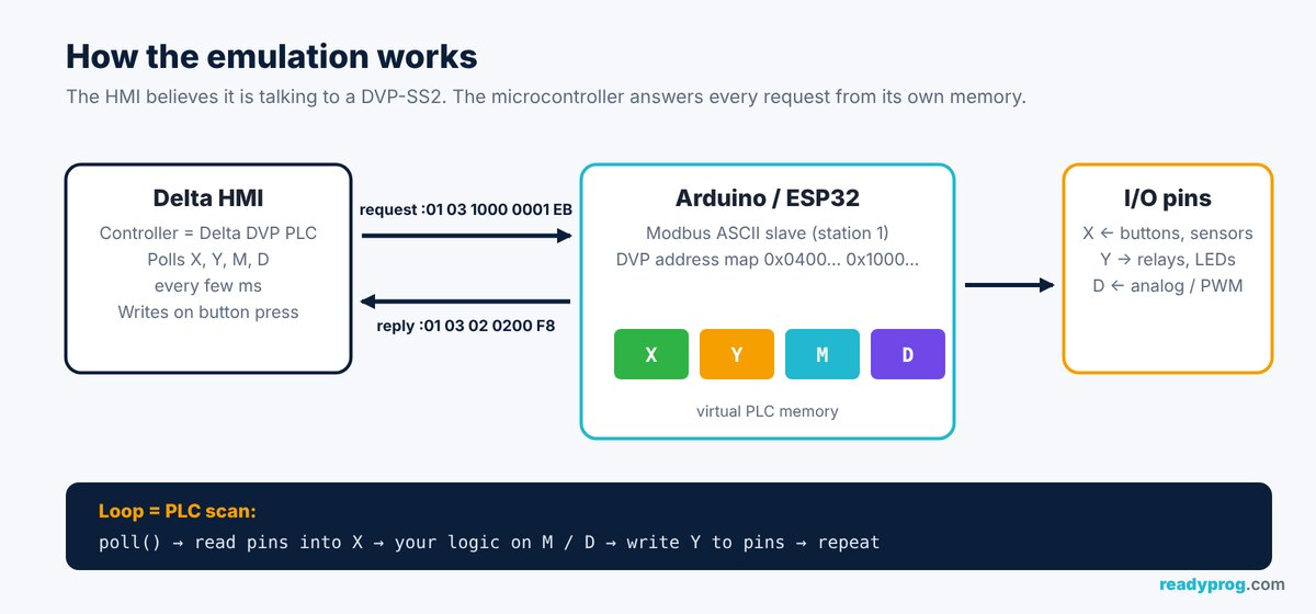
A Delta DVP-SS2 talks to the HMI using Modbus ASCII on its RS232 port. Every few milliseconds the HMI sends a request such as "read D0" or "set M0 ON". Our firmware does three things:
- Receives and checks each frame (start character, station number, LRC checksum).
- Translates the Modbus address back to a PLC device:
0x1000becomes D0,0x0800becomes M0,0x0500becomes Y0. - Answers from a small "virtual PLC memory" inside the microcontroller, then the main loop maps that memory to real pins.
The main loop works like a PLC scan: read pins into X → run your logic on M and D → write Y to the output pins → repeat.
Parts list
| Part | Notes |
|---|---|
| Delta HMI with RS232 COM port | DOP-100 series (DIAScreen) or DOP-B series (DOPSoft) |
| Arduino UNO / NANO / MEGA or ESP32 DevKit | MEGA and ESP32 keep the USB port free for debugging |
| MAX3232 RS232-to-TTL module with DB9 | Works at 3.3 V and 5 V. Do not use the old MAX232 with an ESP32. |
| DB9 cable / 3 wires | Only TXD, RXD and GND are needed |
| Push buttons, LEDs, a potentiometer | For the demo inputs, outputs and analog value |
Wiring the Arduino UNO
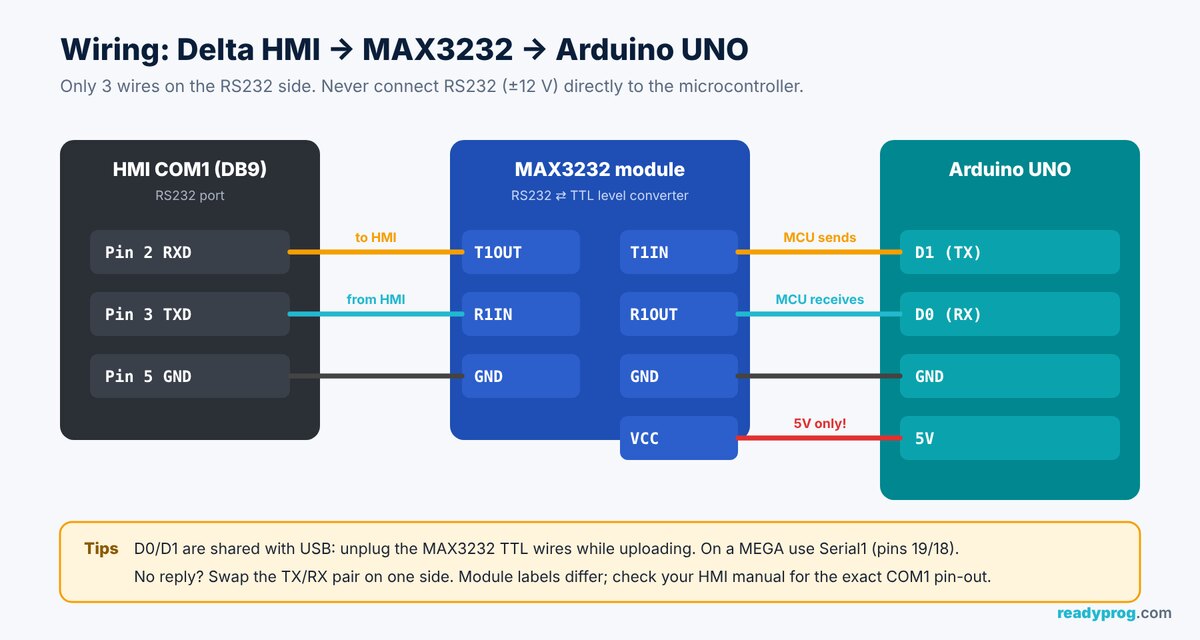
- HMI pin 3 (TXD) → MAX3232 R1IN → R1OUT → Arduino D0 (RX).
- Arduino D1 (TX) → MAX3232 T1IN → T1OUT → HMI pin 2 (RXD).
- GND to GND on both sides. MAX3232 VCC to 5 V.
Important: RS232 uses about ±12 V. Never connect the HMI port directly to a microcontroller pin. On the UNO, pins D0/D1 are shared with USB, so disconnect the MAX3232 while uploading the sketch.
Wiring the ESP32
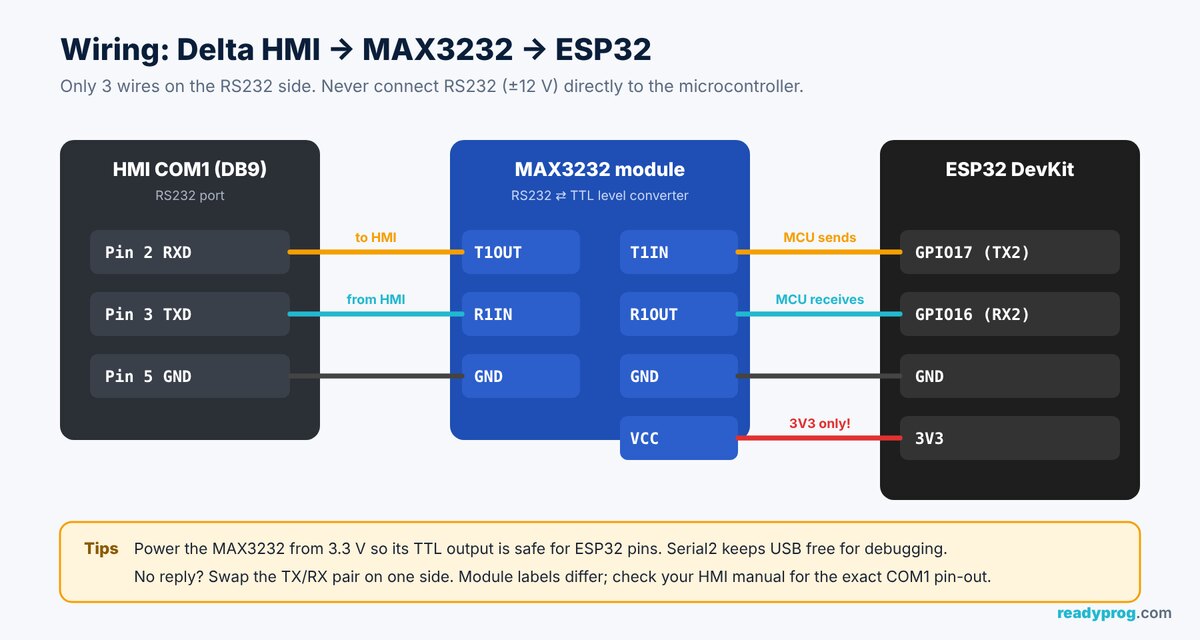
On the ESP32 we use Serial2 (GPIO16 = RX, GPIO17 = TX). Power the MAX3232 from 3.3 V so its TTL output never exceeds the ESP32 pin voltage. The USB port stays free, so you can watch every HMI write in the Serial Monitor.
The Delta DVP-SS2 address map (the heart of the project)
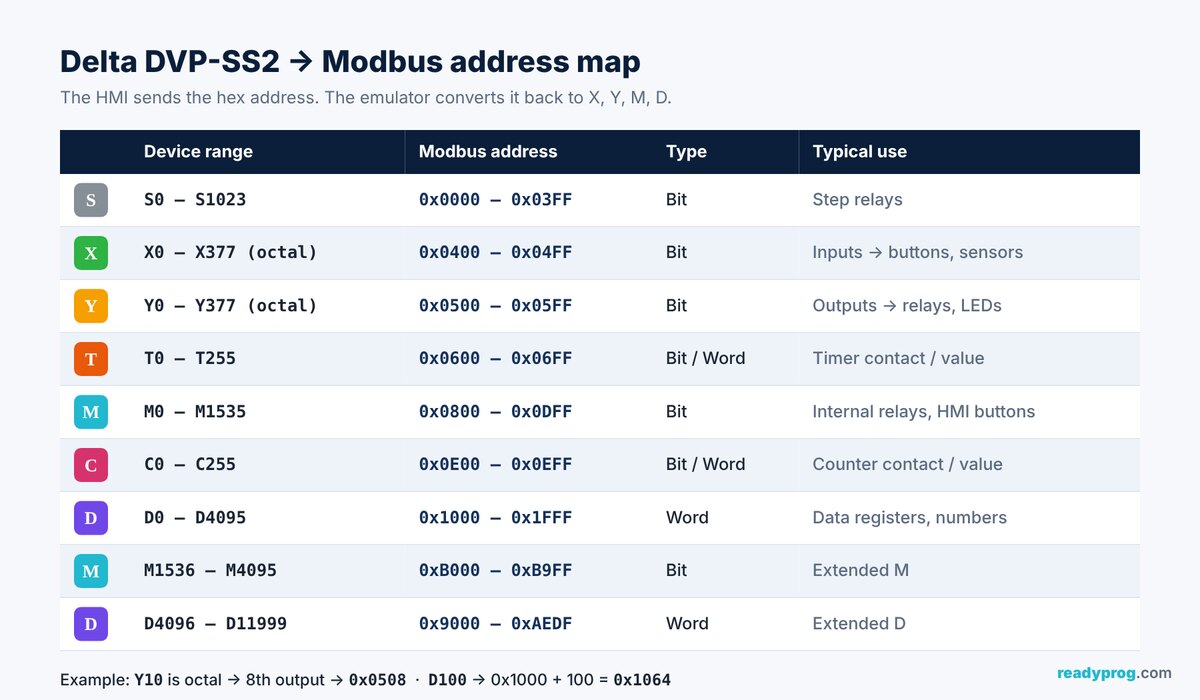
When you place a lamp on Y0 in the HMI, the HMI actually asks for Modbus address 0x0500. The firmware must use the same map as a real DVP, otherwise buttons will move the wrong bits. Two rules people often miss:
- X and Y are octal. There is no X8 or Y9: after Y7 comes Y10, which is the 9th output and address
0x0508. - D registers are 16-bit words. 32-bit values use two registers, low word first (D0 + D1), which is what the HMI expects for "Double Word" objects.
Inside the protocol: one Modbus ASCII frame
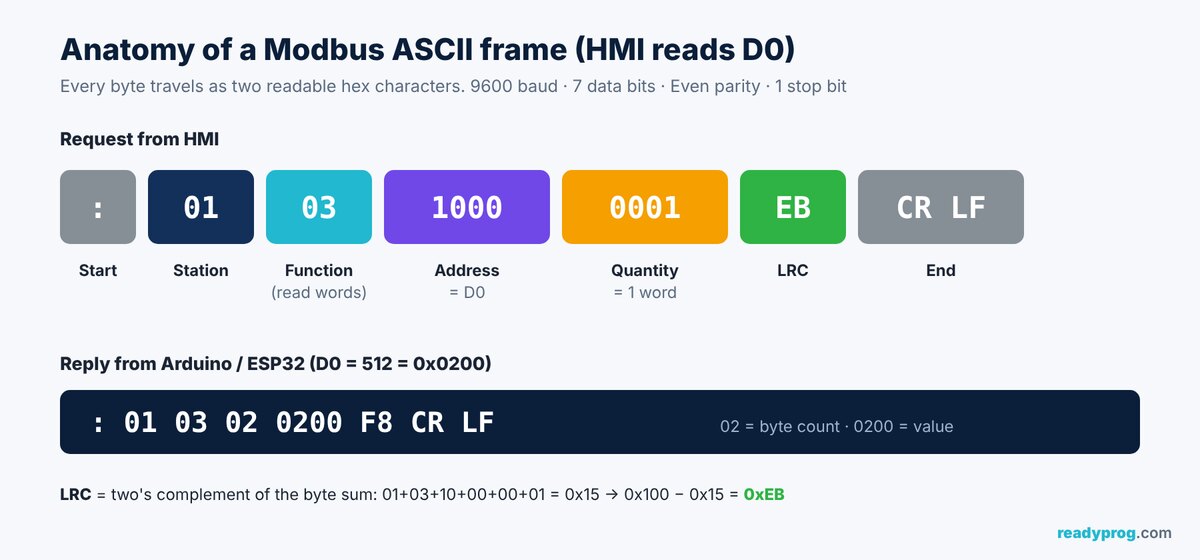
The DVP-SS2 default on COM1 is 9600 baud, 7 data bits, Even parity, 1 stop bit, ASCII mode, station 1. Each byte is sent as two readable hex characters, so you can even watch the traffic with a serial terminal. The firmware supports the function codes the HMI uses:
| Code | Meaning | Used by the HMI for |
|---|---|---|
| 01 / 02 | Read bits | Lamps, bit indicators (X, Y, M, S, T, C) |
| 03 / 04 | Read words | Numeric displays, bar graphs, trends (D, T, C) |
| 05 | Write one bit | Set / Reset / Momentary / Toggle buttons |
| 06 | Write one word | Numeric input |
| 0F / 10 | Write many bits / words | Recipes, multi-word writes, 32-bit values |
Wrong checksums are ignored, requests for other station numbers are ignored, broadcasts are executed without a reply, and an unknown address returns a proper Modbus exception, exactly as a PLC does. The firmware also supports Modbus RTU mode and an RS485 driver-enable pin if you prefer RS485.
Writing the logic: think in ladder, write in C
The firmware gives you simple functions to read and write PLC devices, so your logic reads almost like a ladder rung. The demo implements this classic start/stop circuit:
RUN (M10) = ( START (M0) OR X0 OR RUN (M10) ) AND NOT ( STOP (M1) OR X1 )
Y0        = RUN (M10)
D0        = analog input value
PWM pin   = D10 (typed on the HMI)
D20       = D20 + 1 every second while RUN
On every loop the firmware answers the HMI first, then runs one "scan" of this logic. Because the HMI only polls the memory, the response time is a few milliseconds, which is more than enough for buttons, lamps and numeric values.
Configuring the Delta HMI
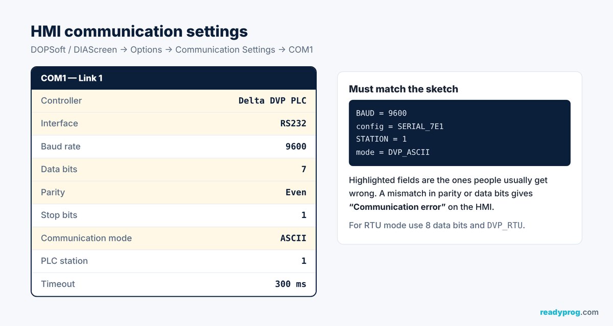
- Create a new project in DIAScreen (DOP-100) or DOPSoft (DOP-B) and choose your HMI model.
- For the controller select Delta DVP PLC on COM1 with interface RS232.
- Set 9600, 7 data bits, Even parity, 1 stop bit, ASCII mode, PLC station 1.
- Download the project to the HMI. If the settings do not match the firmware you will see a "Communication error" message on the screen.
Designing the demo screen
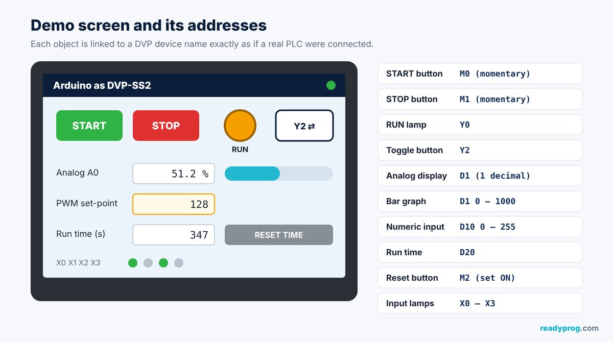
| HMI object | Address | Setting |
|---|---|---|
| START button | M0 | Momentary |
| STOP button | M1 | Momentary |
| RUN lamp | Y0 | Bit lamp |
| Output toggle | Y2 | Toggle (maintained) button |
| Analog display + bar | D1 | Word, 1 decimal place, 0–1000 |
| PWM set-point | D10 | Numeric input, limits 0–255 |
| Run time | D20 | Numeric display |
| Reset run time | M2 | Set ON button |
| Input indicators | X0–X3 | Bit lamps |
Testing and troubleshooting
| Symptom | Likely cause and fix |
|---|---|
| "Communication error" on the HMI | TX/RX swapped (swap one pair), wrong COM port, or 8N1 instead of 7E1. |
| Values appear but buttons do nothing | Button linked to an address outside the emulated memory, or the logic overwrites the bit every scan. |
| Wrong output turns on | Octal numbering: Y10 is the 9th output, not the 11th. |
| Works, then stops after uploading | On the UNO the USB and the MAX3232 share D0/D1. Disconnect the module while uploading. |
| Garbage characters | Missing common GND, or MAX3232 powered from the wrong voltage. |
Limitations (be honest with your project)
- It is not a real PLC: WPLSoft / ISPSoft cannot download ladder to it, and special devices (M1000, D1000 system flags) have no built-in meaning.
- The Arduino UNO has 2 KB of RAM, so it emulates a smaller memory (M0–M511, D0–D199). The ESP32 emulates the full range.
- RS232 cables should stay under about 15 m. For longer distances use the RS485 option.
- Do not use it for safety functions (emergency stop, guards). Those must be hard-wired.
Frequently asked questions
Does it work with DOP-100 (DIAScreen) and DOP-B (DOPSoft)?
Yes. Both families include the Delta DVP PLC driver. Only the menu names differ slightly.
Can I use RS485 instead of RS232?
Yes. Replace the MAX3232 with a MAX485 / MAX3485 module and enable the driver-enable pin in the firmware. Then select RS485 on the HMI port.
Can several HMIs or devices share it?
On RS485 you can give each microcontroller its own station number and connect several on the same line.
Will my HMI project work later with a real DVP-SS2?
Yes, that is the point of using the same driver and address map. Just connect the real PLC with the same communication settings.
Get the complete ready-to-use project
Everything in this article is available as a ready-to-upload package for $49:
- DeltaDVPSlave library: Modbus ASCII + RTU, full DVP-SS2 address map, functions 01–06, 0F, 10, RS485 support.
- Arduino sketch (UNO / NANO / MEGA) and ESP32 sketch with the full demo logic.
- High-resolution wiring diagrams, address map and HMI settings sheets.
- A step-by-step setup guide, including HMI screen settings and troubleshooting.
Prefer to read the full product details first? See the product page.
Have a question, or want this emulation for another PLC brand? Write it in the comments below and tell me which HMI model you are using.
Posted in:
Projects Under Discussion
Related posts
-
A Failed Wi-Fi Gateway for a Delta PLC: What a Packet Log Taught Me About Unverified Assumptions
I designed a sub-$7 wireless programming gateway for a Delta DVP-14SS2 PLC (ESP32, RS-485 transceiver, arbitration...Read more
-
How AI Dictates When Mechanical Parts Must Be Replaced in Automotive and Aerospace
Discover how Edge AI and microcontrollers like the ESP32 are revolutionizing vehicle and aerospace diagnostics. By...Read more
-
How to Connect an Arduino or ESP32 to a Delta DVP PLC with Modbus RTU (RS-485)
Wire an ESP32 or Arduino to a Delta DVP PLC over RS-485, switch COM2 to Modbus RTU, and read or write D, M and Y...Read more
Leave a comment