
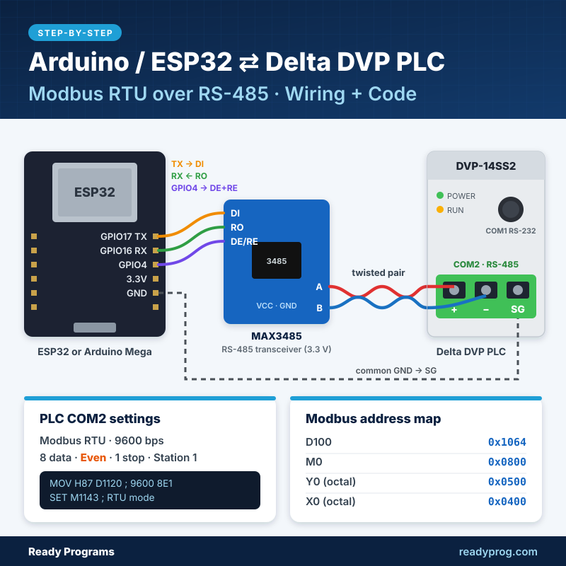
Wire an ESP32 or Arduino to a Delta DVP PLC over RS-485, switch COM2 to Modbus RTU, and read or write D, M and Y...
Latest posts
-
 How to Connect an Arduino or ESP32 to a Delta DVP PLC with Modbus RTU (RS-485)Read more
-
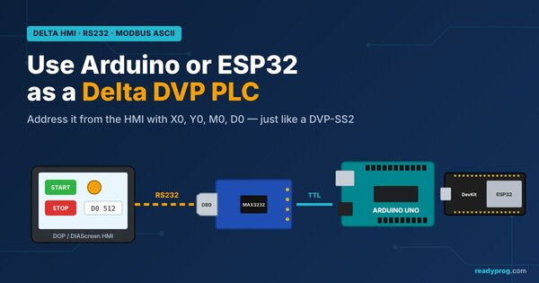 Use Arduino or ESP32 as a Delta DVP PLC: Control It from a Delta HMI via RS232Read more
Turn an Arduino or ESP32 into a Delta DVP-SS2 PLC that your Delta HMI talks to over RS232. Design screens with X0,...
-
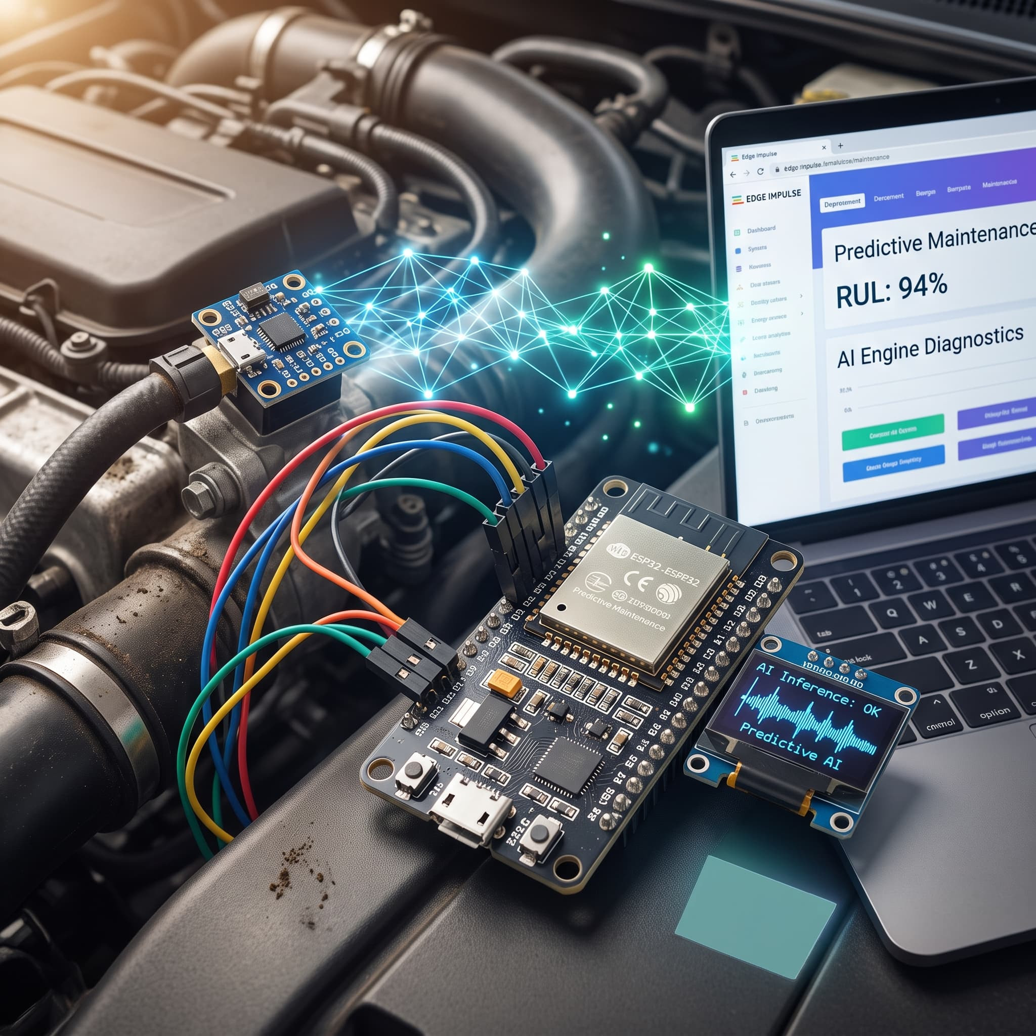 How AI Dictates When Mechanical Parts Must Be Replaced in Automotive and AerospaceRead more
Discover how Edge AI and microcontrollers like the ESP32 are revolutionizing vehicle and aerospace diagnostics. By...
-
 How to Choose a Graduation Project Idea in Computer Science & Software Engineering (2026 Guide)Read more
A practical, step-by-step guide to choosing a winning graduation project idea in computer science or software...
-
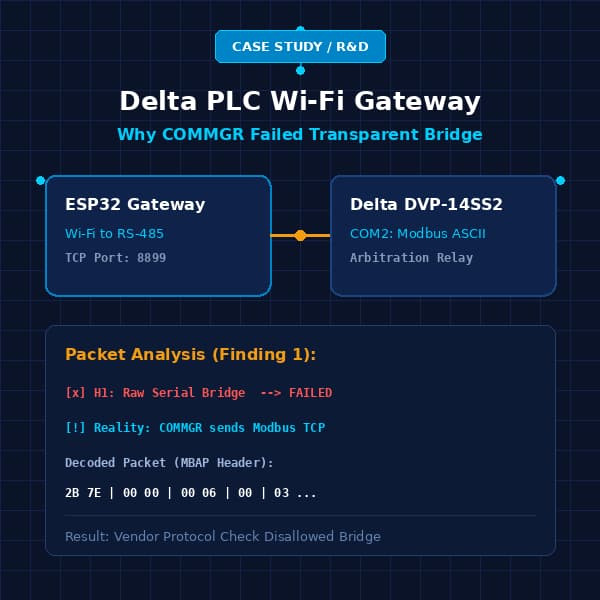 A Failed Wi-Fi Gateway for a Delta PLC: What a Packet Log Taught Me About Unverified AssumptionsRead more
I designed a sub-$7 wireless programming gateway for a Delta DVP-14SS2 PLC (ESP32, RS-485 transceiver, arbitration...
Blog categories
Search in blog
Archived posts
How to Connect an Arduino or ESP32 to a Delta DVP PLC with Modbus RTU (RS-485)
Why connect an Arduino or ESP32 to a Delta PLC?
A Delta DVP PLC is reliable at controlling a machine, but it has no Wi-Fi, no cloud and no easy way to log data. An ESP32 or Arduino fills that gap for a few dollars. Connect the two over RS-485 and the microcontroller can read temperatures and counters from the PLC, push them to a dashboard, or send setpoints back.
The PLC already speaks the protocol you need: Modbus. In this guide you will:
- Wire an ESP32 (or Arduino Mega) to the PLC's RS-485 port.
- Switch the PLC port from Delta's default Modbus ASCII to Modbus RTU.
- Find the correct Modbus address for any D, M, X or Y device.
- Read and write PLC data with the ModbusMaster library.
The example uses a DVP-14SS2, but the same steps work for the ES2, SA2 and SX2 families.
What you need
| Part | Notes |
|---|---|
| Delta DVP PLC with RS-485 (COM2) | DVP-14SS2 used here; ES2, SA2, SX2 work the same way |
| ESP32 dev board (recommended) or Arduino Mega | Needs a hardware UART that supports 8E1 framing |
| RS-485 transceiver module | MAX3485 / SP3485 for 3.3 V boards (ESP32); MAX485 for 5 V boards |
| Twisted-pair cable | Keep it short for testing; add a 120 Ω terminator on long runs |
| WPLSoft or ISPSoft | To download the small port-setup program to the PLC |
Avoid the Arduino Uno for this job. SoftwareSerial cannot generate the even-parity (8E1) framing the PLC uses, so communication fails silently. Use a board with a spare hardware serial port.
Step 1: Wire the ESP32 to the PLC
The transceiver converts the ESP32's UART signals into the differential RS-485 pair the PLC expects.
| From | To | Purpose |
|---|---|---|
| ESP32 GPIO17 (TX2) | Transceiver DI | Data to the PLC |
| ESP32 GPIO16 (RX2) | Transceiver RO | Data from the PLC |
| ESP32 GPIO4 | Transceiver DE + RE (tied together) | Switches between send and receive |
| ESP32 3.3 V / GND | Transceiver VCC / GND | Power |
| Transceiver A | PLC COM2 + | RS-485 data + |
| Transceiver B | PLC COM2 – | RS-485 data – |
| ESP32 GND | PLC SG / 0 V | Common reference |
On an Arduino Mega, use Serial1 (TX1 = pin 18, RX1 = pin 19) and power a MAX485 from 5 V. If nothing answers later, swap A and B once: module makers do not all label them the same way.
Step 2: Switch PLC COM2 to Modbus RTU
Out of the box, both Delta ports run Modbus ASCII, 9600 bps, 7 data bits, even parity, 1 stop bit, station 1. Most microcontroller libraries, including ModbusMaster, speak RTU only. Add these lines at the start of your ladder program:
LD   M1002          ; ON for the first scan only
MOV  H87  D1120     ; COM2: 9600 bps, 8 data bits, Even, 1 stop bit
SET  M1120          ; keep (latch) the COM2 settings
SET  M1143          ; COM2 in RTU mode (OFF = ASCII)
MOV  K1   D1121     ; station number 1
Download the program, then switch the PLC from STOP to RUN. COM1 (RS-232) keeps its default settings, so your programming cable still works.
Special register numbers can differ between models. Check D1120, D1121, M1120 and M1143 in the manual for your exact PLC before using this on a machine.
Step 3: Find the Modbus address of each PLC device
Every PLC device has a fixed Modbus address. Add the device number to its base address:
| Device | Base address (hex) | Example | Address to use in code |
|---|---|---|---|
| D0 – D4095 (data registers) | 0x1000 | D100 | 0x1064 |
| M0 – M1535 (aux. relays) | 0x0800 | M0 | 0x0800 |
| Y0 – Y377 (outputs, octal) | 0x0500 | Y10 | 0x0508 |
| X0 – X377 (inputs, octal) | 0x0400 | X7 | 0x0407 |
| T0 – T255 (timer value) | 0x0600 | T5 | 0x0605 |
Watch the octal numbering. X and Y count X0–X7, then X10–X17. Y10 is the ninth output, so its offset is 8, not 10. This one detail causes more failed projects than any wiring mistake.
Free download: the full address map, covering S, C, the upper M and D ranges, function codes and a troubleshooting checklist, is a 3-page PDF. Subscribe on our homepage and we will email it to you.
Step 4: Read and write PLC data from the ESP32
Install ModbusMaster by Doc Walker from the Arduino Library Manager, then upload this sketch:
#include <ModbusMaster.h>

#define RS485_DE_RE 4      // DE + RE pins of the transceiver
ModbusMaster plc;

void preTransmission()  { digitalWrite(RS485_DE_RE, HIGH); }  // send
void postTransmission() { digitalWrite(RS485_DE_RE, LOW);  }  // receive

void setup() {
  Serial.begin(115200);
  pinMode(RS485_DE_RE, OUTPUT);
  digitalWrite(RS485_DE_RE, LOW);

  // 9600 bps, 8 data bits, Even parity, 1 stop bit  (RX = 16, TX = 17)
  Serial2.begin(9600, SERIAL_8E1, 16, 17);

  plc.begin(1, Serial2);               // PLC station number 1
  plc.preTransmission(preTransmission);
  plc.postTransmission(postTransmission);
}

void loop() {
  // Read D100 (0x1000 + 100 = 0x1064)
  uint8_t r = plc.readHoldingRegisters(0x1064, 1);
  if (r == plc.ku8MBSuccess) {
    Serial.printf("D100 = %u\n", plc.getResponseBuffer(0));
  } else {
    Serial.printf("Read error: 0x%02X\n", r);
  }

  // Write uptime in seconds to D200 (0x10C8)
  plc.writeSingleRegister(0x10C8, (millis() / 1000) & 0xFFFF);

  // Turn M0 ON (0x0800)
  plc.writeSingleCoil(0x0800, 1);

  // Read outputs Y0-Y7 (0x0500)
  r = plc.readCoils(0x0500, 8);
  if (r == plc.ku8MBSuccess) {
    Serial.printf("Y0-Y7 = 0x%02X\n", plc.getResponseBuffer(0) & 0xFF);
  }

  delay(1000);
}
To test it, add a rung in the PLC that moves a value into D100, and another that uses M0 to drive Y0. Open the Serial Monitor at 115200 baud: you should see D100's value, and Y0 should switch on.
On an Arduino Mega, replace Serial2.begin(...) with Serial1.begin(9600, SERIAL_8E1); and use Serial1 in plc.begin(). Replace Serial.printf with Serial.print, since the Mega has no printf.
Troubleshooting
| Symptom | Likely cause | Fix |
|---|---|---|
| Error 0xE2 (response timed out) | Settings mismatch, A/B swapped, or DE/RE not switching | Confirm 9600 8E1 RTU on both sides; swap A and B; check GPIO4 wiring |
| Error 0xE3 (invalid CRC) | Noise or wrong parity | Use twisted pair, add a 120 Ω terminator, recheck SERIAL_8E1 |
| Exception 0x02 (illegal data address) | Wrong address or device out of range | Recalculate with the base table; remember X/Y are octal |
| Works once, then stops | Another master on COM2 (an HMI) | Only one master per RS-485 line |
| PLC ignores the new settings | Port program did not run | Switch STOP → RUN, or power-cycle the PLC |
FAQ
Can I keep the default ASCII mode instead? Yes, but you need a Modbus library that supports ASCII. RTU is faster and better supported, so most projects switch.
Can the HMI and the ESP32 share the PLC? Not on the same port as two masters. Connect the HMI to COM1 (RS-232) and the ESP32 to COM2 (RS-485).
How do I read a 32-bit value? Read two registers at once. Delta stores the low word first: D100 is the low word and D101 the high word.
Next steps
Your ESP32 now reads and writes Delta PLC data over Modbus RTU. From here you can publish the values to a web dashboard, log them to the cloud, or add Wi-Fi alarms to an existing machine without touching its wiring.
Want to go the other way and make a Delta HMI control an Arduino or ESP32 as if it were a PLC? See our ready-made project: Arduino and ESP32 as a Delta DVP PLC: Control from Delta HMI via RS232.
Browse more tested PLC, Arduino and ESP32 projects with full source code and wiring diagrams.
Posted in:
Projects Under Discussion
Related posts
-
A Failed Wi-Fi Gateway for a Delta PLC: What a Packet Log Taught Me About Unverified Assumptions
I designed a sub-$7 wireless programming gateway for a Delta DVP-14SS2 PLC (ESP32, RS-485 transceiver, arbitration...Read more
-
How AI Dictates When Mechanical Parts Must Be Replaced in Automotive and Aerospace
Discover how Edge AI and microcontrollers like the ESP32 are revolutionizing vehicle and aerospace diagnostics. By...Read more
-
Use Arduino or ESP32 as a Delta DVP PLC: Control It from a Delta HMI via RS232
Turn an Arduino or ESP32 into a Delta DVP-SS2 PLC that your Delta HMI talks to over RS232. Design screens with X0,...Read more
Leave a comment